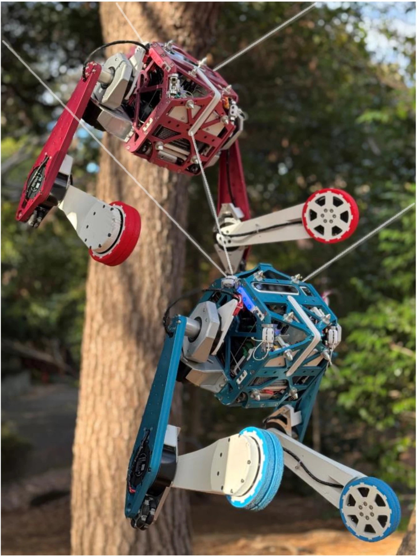
TwinX extends parallel wire actuation to two floating bodies connected by a single inter-body wire.
Abstract
Parallel wire-driven systems are a framework in which multiple wires are connected to an end effector, and the end effector is driven by the tensions of those wires. Because they can transmit large forces, up to the breaking strength of the wires, over lengths on the order of several tens of meters, they can realize powerful actuation in large workspaces. In recent years, studies have also investigated connecting wires to external environments such as trees and columns and forming parallel wire actuation on site. However, conventional parallel wire-driven systems often assume a single end effector, and because of interference between wires and links in a shared workspace, it has been difficult to handle multiple floating links simultaneously. In this study, we realize multi-floating-link parallel wire actuation by introducing an inter-body wire. In real-robot experiments, the two bodies supported and lifted a mannequin and transferred it onto a stretcher as a rescue motion. This shows that parallel wire actuation can be extended from a single end effector to a multi-floating-link system, and indicates its potential for broader tasks such as the manipulation of large objects and rescue support.
Research Concept: Connecting the Floating Bodies
Conventional cable-driven parallel robots typically actuate a single floating end effector. TwinX connects two robot bodies to the environment and to each other, allowing them to support an object at multiple points within a shared workspace. The inter-body wire supplies an additional tension direction without requiring another environmental anchor.
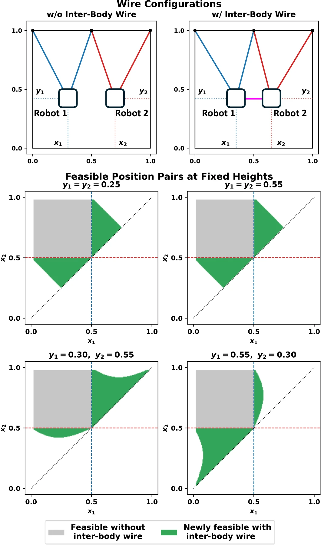
The representative planar model below treats each body as a point mass and each wire as a tension-only connection. A pair of body positions is feasible when wire tensions can balance gravity. At fixed body heights, the gray regions are feasible without the inter-body wire; the green regions become feasible when it is added. These plots illustrate the effect for the studied configurations, rather than guaranteeing arbitrary motion in three dimensions.
Paper Fig. 2. The inter-body connection expands feasible body-position pairs in a representative planar model.
Hardware: From Wheeled Locomotion to Suspended Manipulation
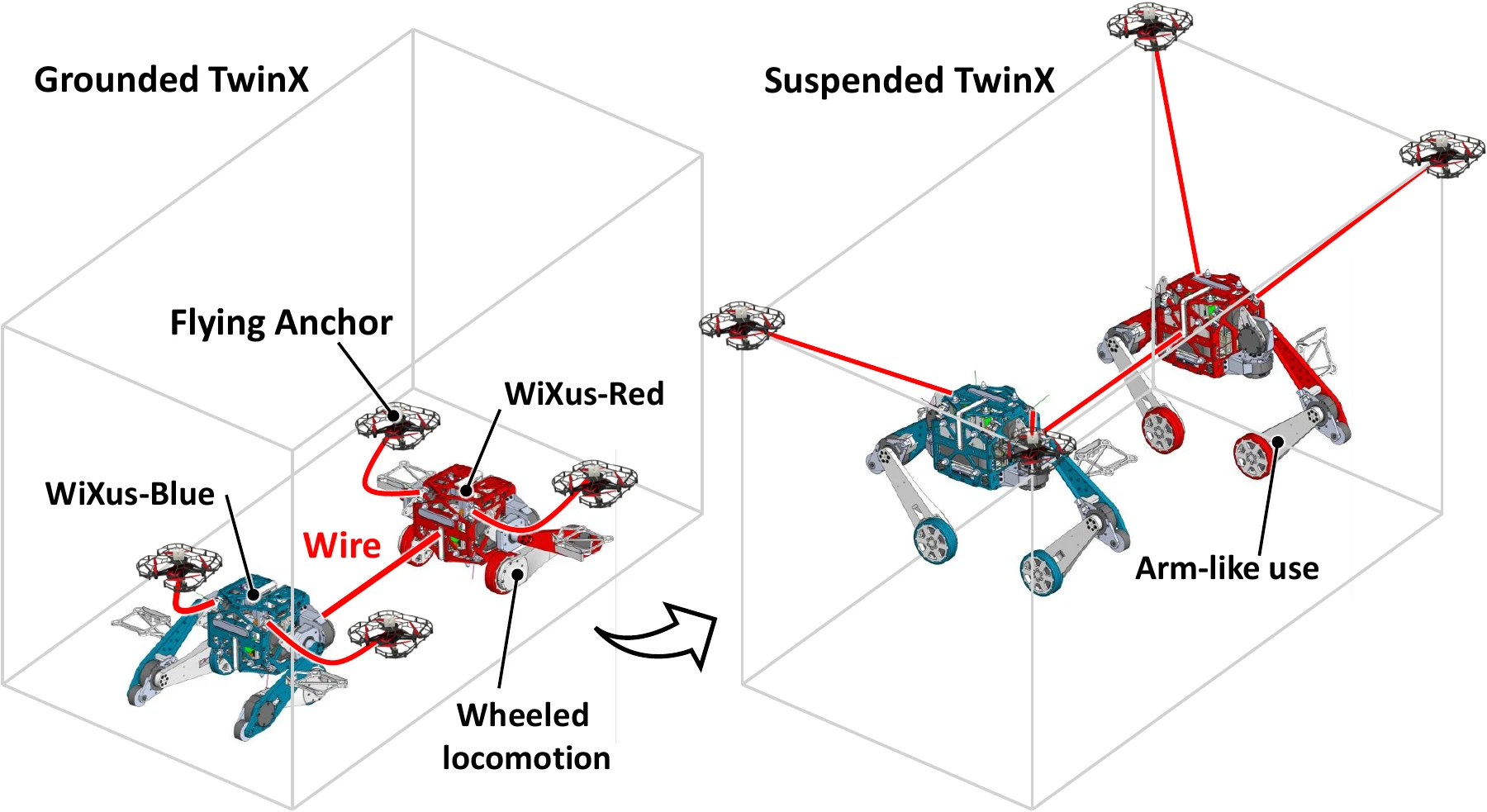
TwinX consists of two identically configured wheeled-legged robots, WiXus-Blue and WiXus-Red. Each carries its own computer, battery, and cameras, and can connect up to four body-mounted wires to the environment. Flying anchors combine drones and anchors to deploy these connections at the task site.
Paper Fig. 3. Ground locomotion and wire-supported operation share the same pair of robot bodies.
The inter-body wire is wound by WiXus-Blue and has a maximum continuous tension of approximately 400 N. The environmental wire-winding modules provide approximately 120 N each. Once the bodies are suspended, their wheeled legs are freed from ground support and can act as arms. Winding the inter-body wire also draws the bodies together for docking and a vehicle configuration.
Coupled Wire Geometry and Wrench Mapping
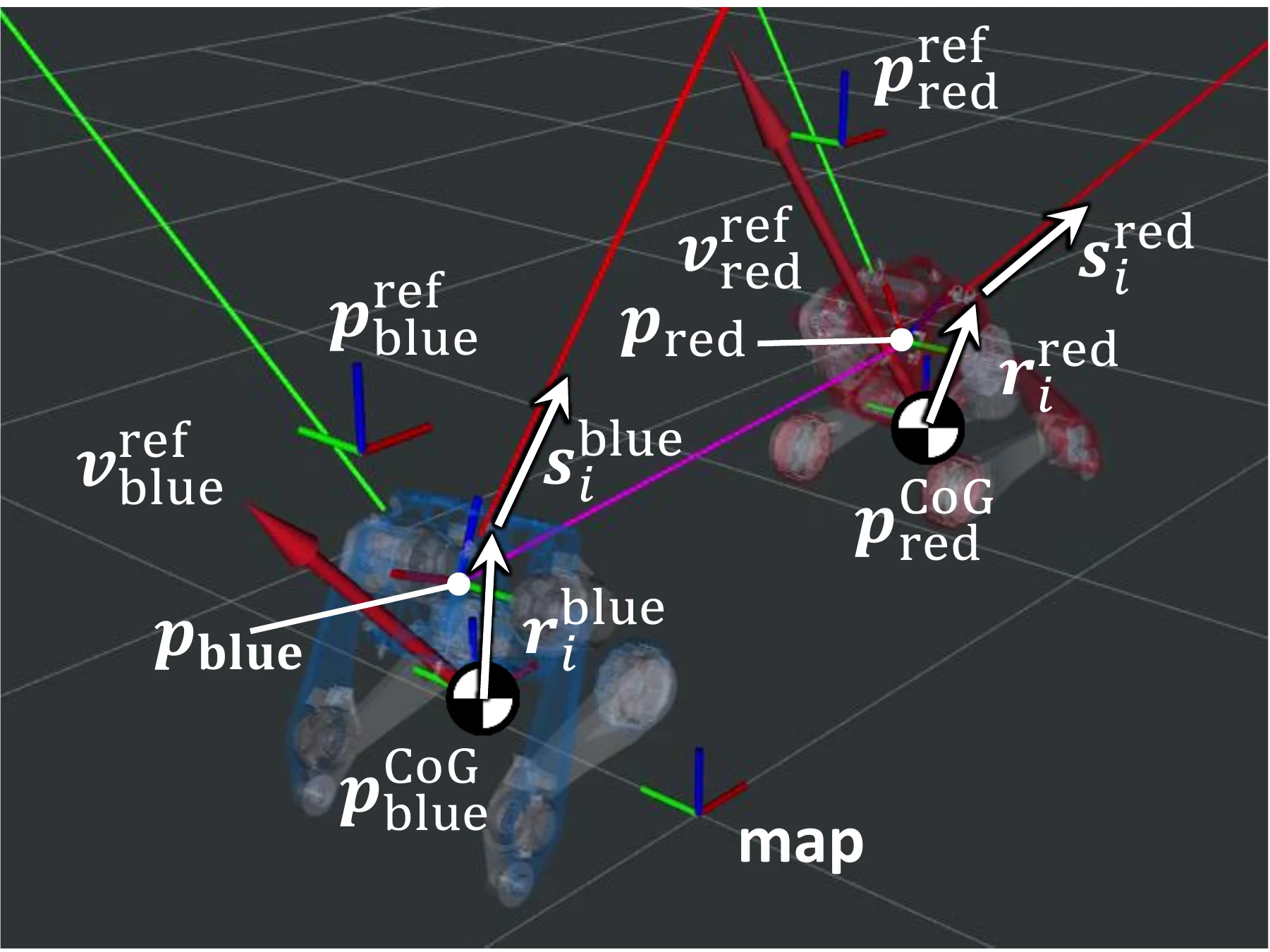
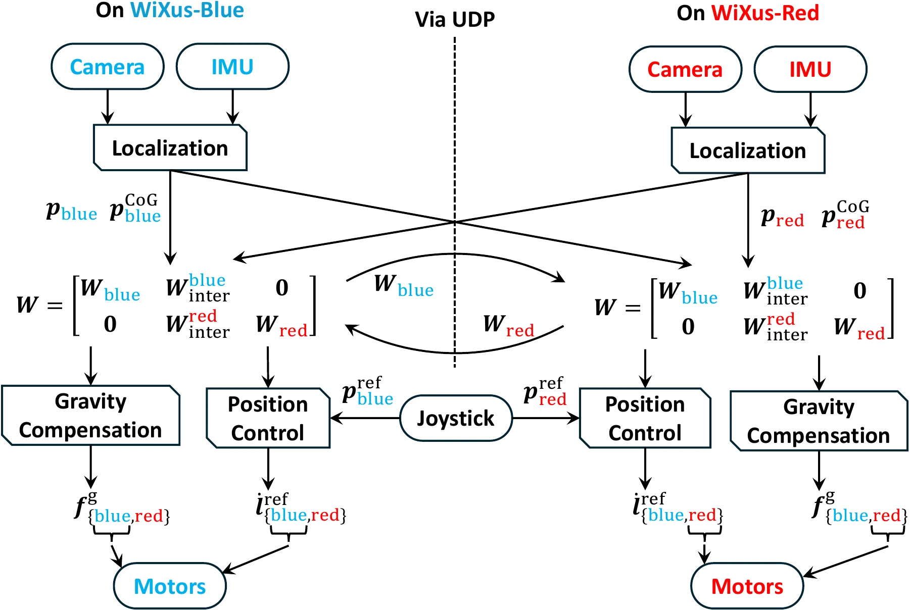
The controller stacks the six-dimensional wrenches of both bodies and relates them to all wire tensions through a whole-system Jacobian. Environmental wire columns act on their own body; the shared inter-body column acts on both bodies with opposite force directions. Each column includes the wire direction and the moment generated at its attachment point.
Paper Fig. 4. Both robots describe wire geometry in a shared RTAB-Map coordinate frame.
With l environmental wires on WiXus-Blue and m on WiXus-Red, W has 12 rows and l + 1 + m columns. The shared geometry explicitly couples the bodies through the inter-body tension. The experimental configuration uses four environmental wires and one inter-body wire, so the suspended system is underactuated.
Gravity Compensation and Distributed Control
A quadratic program computes gravity-compensation tensions by minimizing the wrench residual subject to minimum and maximum tension bounds. Position feedback uses each body's center of mass, calculated from the robot model and joint angles, to produce translational velocity commands. Wire-velocity feedback then adjusts the gravity-compensation tensions to follow these commands; the reference angular velocities are set to zero.
Paper Fig. 5. Each robot computes control for the coupled system and applies only its own actuator commands.
Both robots localize in a common RTAB-Map and exchange localization outputs and Jacobian components via UDP at 200 Hz. The main controller runs at 50 Hz using the latest received values. Each robot computes commands for the entire system but sends only its own components to its motors; WiXus-Blue also drives the inter-body wire. In the physical experiment, target positions are updated using a joystick.
Experiments
In MuJoCo, target-position sequences tested both preserved and changing relative positions, using minimum-jerk transitions. The controller followed the sequences without breakdown, with position errors roughly on the order of 0.1 m. Errors increased near or outside the feasible range of the wire arrangement.
The physical demonstration uses a 5 kg, 150 cm mannequin, four ceiling pillars, and a stretcher. Four environmental wires and the inter-body wire support cooperative lifting and transfer. The clips below show the four phases of the rescue demonstration; the speed labels are retained from the source footage.
Phase 1. Attaching Wires to the Environment
Four flying anchors deploy two wires from each robot to the ceiling pillars. WiXus-Red observes and controls the anchors using its RGB-D camera; the two robot bodies localize in a shared map. The pillar positions are measured in advance. Footage: 8× speed.
Phase 2. Supporting and Transferring the Mannequin
The two suspended bodies support the mannequin at two points, lift it with their legs acting as arms, and transfer it onto the stretcher. Cooperative wire actuation changes their body positions during the task. Footage: 4× speed.
Phase 3. Detaching the Environmental Wires
An operator manually moves each WiXus to reverse the tying motion while checking the wire routing. Once untied, the flying anchors are recovered by retracting the wires. This phase is manually operated, without a pre-programmed reverse trajectory. Footage: 8× speed.
Phase 4. Transporting the Stretcher
TwinX winds the inter-body wire to form a vehicle configuration, then tows the loaded stretcher by winding the wire deployed from WiXus-Red. Footage: 4× speed.
Observed Limitations
The study demonstrates a mannequin rescue scenario. Tracking is constrained by wire geometry and available tensions: WiXus-Red shows intervals of insufficient tracking and reaches the experiment's 100 N software tension limit. Suspended motion can also destabilize visual localization. Wrench-aware trajectory planning, anchor arrangement optimization, integrated state estimation, and systematic communication-delay and packet-loss evaluation remain future work.
BibTeX
@article{inoue2026extending,
  title = {Extending Wire-Driven Parallel Robots to Multi-Floating-Link Systems With an Inter-Body Wire},
  author = {Inoue, Shintaro and Kawaharazuka, Kento and Suzuki, Temma and Yuzaki, Sota and Yoneda, Keita and Okada, Kei},
  journal = {IEEE Robotics and Automation Letters},
  year = {2026},
  volume = {11},
  number = {10},
  pages = {11314--11321},
  doi = {10.1109/LRA.2026.3723331}
}